
 | Festkörper - durch Rotation |
 | Revolved Area Solid |
 | Solide de révolution surfacique |
| Item | SPF | XML | Change | Description | IFC2x3 to IFC4 |
|---|---|---|---|---|
| IfcRevolvedAreaSolid | ||||
| Position | MODIFIED | Instantiation changed to OPTIONAL. |
An IfcRevolvedAreaSolid is a solid created by revolving a cross section provided by a profile definition about an axis.
The resulting solid is positioned by the IfcSweptAreaSolid.Position relative to the object coordinate system. If provided, it allows to reposition the revolved solid. If not provided, it defaults to the current object coordinate system. The axis and the cross section shall be in the same plane, prior to any repositioning.
NOTE Both the axis and the cross section are required to lie in the xy plane of the object position coordinate system.
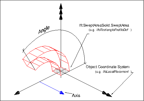 |
EXAMPLE Figure 343 illustrates geometric parameters of the revolved solid. The revolved area solid defines the revolution of a 2D area (given by a profile definition) by an axis and angle. The result is a solid. The swept area is given by a profile definition.
The AxisLine can have any orientation within the XY plane, it does not have to be parallel to the y-axis as shown in the illustration. |
|
Figure 343 — Revolved area solid geometry |
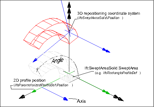 |
EXAMPLE Figure 1 illustrates geometric parameters and additional positioning parameters of the revolved area solid. The revolved area solid defines the rotation of a 2D area by an axis and angle. The 2D area, provided by a parameterized profile definition, can be positioned relative to the object coordinate system (other then by default at 0.,0. with no rotation). The result is a solid that can be repositioned within the object coordinate system.
|
|
Figure 344 — Repositioned revolved area solid geometry |
NOTE Definition according to ISO/CD 10303-42:1992
A revolved area solid is a solid formed by revolving a planar bounded surface about an axis. The axis shall be in the plane of the surface and the axis shall not intersect the interior of the bounded surface. The bounded surface may have holes which will sweep into holes in the solid. The direction of revolution is clockwise when viewed along the axis in the positive direction. More precisely if A is the axis location and d is the axis direction and C is an arc on the surface of revolution generated by an arbitrary point p on the boundary of the swept area, then C leaves p in direction d x (p - A) as the area is revolved.
NOTE Entity adapted from revolved_area_solid defined in ISO 10303-42.
HISTORY New entity in IFC1.5
Informal Propositions:
Texture Use Definition
For side faces, textures are aligned facing upright along the sides with origin at the first point of an arbitrary profile, and following the outer bound of the profile counter-clockwise (as seen from above). For parameterized profiles, the origin is defined at the +Y extent for rounded profiles (having no sharp edge) and the first sharp edge counter-clockwise from the +Y extent for all other profiles. Textures are stretched or repeated on each side along the outer boundary of the profile according to RepeatS. Textures are stretched or repeated on each side along the outermost (longest) revolution path according to RepeatT, where coordinates are compressed towards the axis of revolution.
For top and bottom caps, textures are aligned facing front-to-back, with the origin at the minimum X and Y extent. Textures are stretched or repeated on the top and bottom to the extent of each face according to RepeatS and RepeatT.
For profiles with voids, textures are aligned facing upright along the inner side with origin at the first point of an arbitrary profile, and following the inner bound of the profile clockwise (as seen from above). For parameterized profiles, the origin of inner sides is defined at the +Y extent for rounded profiles (having no sharp edge such as hollow ellipses or rounded rectangles) and the first sharp edge clockwise from the +Y extent for all other profiles.
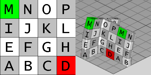 |
Figure 345 illustrates default texture mapping with a repeated texture (RepeatS=True and RepeatT=True). The image on the left shows the texture where the S axis points to the right and the T axis points up. The image on the right shows the texture applied to the geometry where the X axis points back to the right, the Y axis points back to the left, and the Z axis points up. For an IfcRevolvedAreaSolid having a profile of IfcTShapeProfileDef and revolved at 22.5 degrees, the side texture coordinate origin is the first corner counter-clockwise from the +Y axis, which equals |
|
Figure 345 — Revolved area solid textures |
| # | Attribute | Type | Cardinality | Description | G |
|---|---|---|---|---|---|
| 3 | Axis | IfcAxis1Placement | Axis about which revolution will take place. | X | |
| 4 | Angle | IfcPlaneAngleMeasure | The angle through which the sweep will be made. This angle is measured from the plane of the swept area provided by the XY plane of the position coordinate system. | X | |
| AxisLine :=IfcRepresentationItem() || IfcGeometricRepresentationItem () || IfcCurve() || IfcLine(Axis.Location, IfcRepresentationItem() || IfcGeometricRepresentationItem () || IfcVector(Axis.Z,1.0)) | IfcLine | The line of the axis of revolution. | X |
| Rule | Description |
|---|---|
| AxisStartInXY | The start of the axis shall lie in the XY plane of the position coordinate system. |
| AxisDirectionInXY | The direction of the axis shall be parallel to the XY plane of the position coordinate system. |
| # | Attribute | Type | Cardinality | Description | G |
|---|---|---|---|---|---|
| IfcRepresentationItem | |||||
| LayerAssignment | IfcPresentationLayerAssignment @AssignedItems | S[0:1] | Assignment of the representation item to a single or multiple layer(s). The LayerAssignments can override a LayerAssignments of the IfcRepresentation it is used within the list of Items.
IFC2x3 CHANGE The inverse attribute LayerAssignments has been added. IFC4 CHANGE The inverse attribute LayerAssignment has been restricted to max 1. Upward compatibility for file based exchange is guaranteed. | X | |
| StyledByItem | IfcStyledItem @Item | S[0:1] | Reference to the IfcStyledItem that provides presentation information to the representation, e.g. a curve style, including colour and thickness to a geometric curve.
IFC2x3 CHANGE The inverse attribute StyledByItem has been added. | X | |
| IfcGeometricRepresentationItem | |||||
| IfcSolidModel | |||||
| Dim :=3 | IfcDimensionCount | The space dimensionality of this class, it is always 3. | X | ||
| IfcSweptAreaSolid | |||||
| 1 | SweptArea | IfcProfileDef | The surface defining the area to be swept. It is given as a profile definition within the xy plane of the position coordinate system. | X | |
| 2 | Position | IfcAxis2Placement3D | ? |
Position coordinate system for the resulting swept solid of the sweeping operation. The position coordinate system allows for re-positioning of the swept solid. If not provided, the swept solid remains within the position as determined by the cross section or by the directrix used for the sweeping operation.
IFC4 CHANGE The attribute has been changed to OPTIONAL with upward compatibility for file-based exchange. | X |
| IfcRevolvedAreaSolid | |||||
| 3 | Axis | IfcAxis1Placement | Axis about which revolution will take place. | X | |
| 4 | Angle | IfcPlaneAngleMeasure | The angle through which the sweep will be made. This angle is measured from the plane of the swept area provided by the XY plane of the position coordinate system. | X | |
| AxisLine :=IfcRepresentationItem() || IfcGeometricRepresentationItem () || IfcCurve() || IfcLine(Axis.Location, IfcRepresentationItem() || IfcGeometricRepresentationItem () || IfcVector(Axis.Z,1.0)) | IfcLine | The line of the axis of revolution. | X | ||
 <xs:element name="IfcRevolvedAreaSolid" type="ifc:IfcRevolvedAreaSolid" substitutionGroup="ifc:IfcSweptAreaSolid" nillable="true"/>

 <xs:complexType name="IfcRevolvedAreaSolid">

  <xs:complexContent>

   <xs:extension base="ifc:IfcSweptAreaSolid">

    <xs:sequence>

     <xs:element name="Axis" type="ifc:IfcAxis1Placement" nillable="true"/>

    </xs:sequence>

    <xs:attribute name="Angle" type="ifc:IfcPlaneAngleMeasure" use="optional"/>

   </xs:extension>

  </xs:complexContent>

 </xs:complexType>
ENTITY IfcRevolvedAreaSolid
SUPERTYPE OF(IfcRevolvedAreaSolidTapered)
SUBTYPE OF (IfcSweptAreaSolid);
Axis : IfcAxis1Placement;
Angle : IfcPlaneAngleMeasure;
DERIVE
AxisLine : IfcLine := IfcRepresentationItem() || IfcGeometricRepresentationItem () || IfcCurve() || IfcLine(Axis.Location,
IfcRepresentationItem() || IfcGeometricRepresentationItem () || IfcVector(Axis.Z,1.0));
WHERE
AxisStartInXY : Axis.Location.Coordinates[3] = 0.0;
AxisDirectionInXY : Axis.Z.DirectionRatios[3] = 0.0;
END_ENTITY;
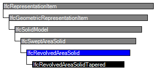
 EXPRESS-G diagram
 Link to this page